Take your preparation offline
20 questions to practise offline.
Free 31-page PDF with model answers, examiner tips and a 4-week preparation plan.
Navigation principles, charts, calculations, and flight planning.
Heading is the direction the aircraft's nose points; track is its path over the ground. Wind can make them differ.
True airspeed is speed through the air mass; groundspeed is speed relative to the surface. The wind vector connects them.
Compare the access plans to open the complete answer library for your selected period.
Compare access plansCompare the access plans to open the complete answer library for your selected period.
Compare access plansThe Lambert Conformal Conic projection is a conic projection that maintains conformality, meaning it preserves angles and small shapes. Meridians are straight lines converging at a pole, and parallels are arcs of concentric circles. It offers minimal distortion over mid-latitude regions, which makes it ideal for aeronautical charts used in continental navigation.
Compare the access plans to open the complete answer library for your selected period.
Compare access plansCompare the access plans to open the complete answer library for your selected period.
Compare access plansNo. The “+V” indicates advisory vertical guidance, not an upgrade of the procedure's approved minima. It can help produce a steady descent, but the pilot must still comply with the LNAV altitude restrictions and MDA, using the barometric altimeter as the primary altitude reference. A drawn glidepath does not authorize descent below MDA or guarantee clearance of obstacles in the visual segment. The important distinction is the approved level of service being flown, not simply whether a vertical needle appears on the display.
Scope: FAA RNAV (GPS) approaches; avionics using LNAV+V notation.
Sources
The same identifier can be assigned to different navigation facilities in different parts of the world. The database must distinguish them using additional geographical information, and the navigator may present a choice of entries. Selecting the familiar letters without checking location can therefore create a route to the wrong facility. Verify the intended region and position, and check that the resulting direction and distance make sense for the clearance. An identifier is a useful label, but it is not always a globally unique location.
Scope: General navigation database selection principle; exact duplicate-selection interface varies.
Sources
No. The decision altitude controls the decision; distance zero is not a substitute for it. On the WAAS LPV and LNAV/VNAV presentations described by the FAA, along-track distance is normally referenced to a point at the runway threshold. The aircraft reaches DA before that point during a normal descent. If the required visual references have not been established at DA, initiate the missed approach as required instead of continuing toward zero distance. Always identify what the displayed distance is actually measuring during the briefing.
Scope: FAA WAAS LPV/LNAV-VNAV approach presentations and U.S. approach requirements.
Sources
CPDLC is valuable for routine, non-urgent exchanges: written messages reduce pressure on busy voice frequencies and provide information the crew can review. Immediate intervention still needs a communication method suited to the urgency, and datalink exchanges can involve delivery, reading and response delays. EUROCONTROL guidance preserves voice for immediate-action messages and requires crews to revert to voice when necessary. The choice is driven by operational time-criticality and clarity, not merely whether the aircraft has an active datalink connection. Company procedures govern how crews manage both channels.
Scope: European en-route CPDLC practices; not a claim about every future datalink application.
Sources
No. Database currency describes the data cycle, not the live operational status of every procedure, airport or navigation aid. A stored approach can be affected by a NOTAM, a database correction notice or an airport closure that does not remove its coding immediately. The FAA handbook even describes indefinitely closed airports remaining in navigation databases. Check operational notices and relevant supplier advisories as well as the validity dates. Successful loading of an approach proves that the data are present, not that the procedure can be used now.
Scope: General database limitation, illustrated by FAA publication; current local NOTAMs govern actual availability.
Sources
That display is derived from how rapidly the distance to the DME station changes. On a constant-radius arc at constant altitude, the distance remains nearly constant even though the aircraft is moving quickly around the station. The displayed closing speed can therefore be very small. DME-derived groundspeed is meaningful as aircraft groundspeed when tracking directly toward or away from the station, with the usual geometric limitations. Do not confuse this range-rate display with a GNSS/FMS groundspeed solution that measures movement along the actual flightpath.
Scope: Conventional DME range-rate speed display; not DME-updated RNAV/FMS groundspeed.
Sources
There is a fourth unknown: the receiver's clock error. The receiver estimates distance from signal travel time, but its clock is not an onboard atomic clock perfectly synchronized with GPS time. A common timing error therefore contaminates every measured range. Measurements from a fourth satellite allow the receiver to solve for clock offset together with three-dimensional position. Additional satellites can improve geometry and enable integrity checks, but having the four measurements needed for a position is not the same as having enough redundancy for aviation integrity monitoring.
Scope: Basic standalone GPS positioning; excludes externally constrained special solutions.
Sources
No. LPV describes the performance of the approach guidance, not the presence of an ILS localizer. An approved satellite-based augmentation receiver uses augmented GNSS to generate lateral and vertical guidance. In the United States, WAAS provides that augmentation, and the approach can be published without a local navigation transmitter at the airport. The guidance presentation can resemble an ILS, but the underlying infrastructure and required airborne approval are different. An ILS-capable aircraft is therefore not automatically equipped or approved to fly LPV minima.
Scope: SBAS LPV concept; WAAS is the U.S. example.
Sources
No. A plausible cockpit indication cannot override a published unusable status. A ground navigation transmitter can produce momentary misleading indications when its primary signal generator is inoperative. The FAA therefore directs pilots to disregard navigation indications from a transmitter identified as unusable or inoperative, even if the display looks normal. Check the applicable NOTAM and use an available, authorized means of navigation. The technical lesson is that a receiver displaying a signal and a facility providing a valid navigation service are different things.
Scope: FAA guidance for ground navigation aids; not an aircraft-specific failure procedure.
Sources
VOR is significantly less prone to errors compared to NDB.
NDBs (Non-Directional Beacons) operate in the low-frequency range and are subject to several types of interference, including:
In contrast, VORs use VHF signals, which are line-of-sight and far less susceptible to environmental distortion. This makes VORs more reliable and accurate for navigation, particularly in enroute or approach phases.
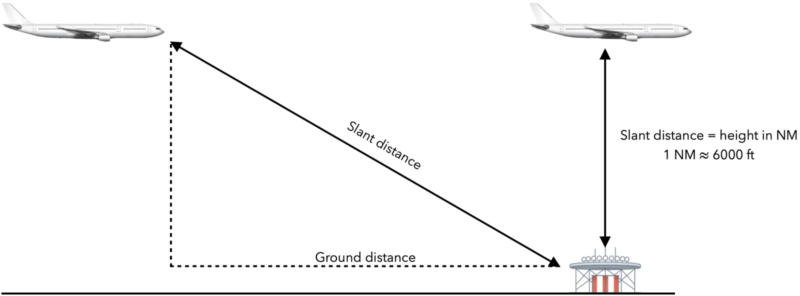
DME provides the slant range distance, which is the straight-line distance between the aircraft’s DME receiver and the ground-based DME transmitter. This is not the same as the horizontal ground distance.
The slant range error becomes most significant when the aircraft is directly overhead the DME station. In that case, the DME reading corresponds approximately to the aircraft's altitude in nautical miles (e.g. at 6,000 ft, it shows about 1 NM; at 30,000 ft, about 5 NM).
As the aircraft moves farther from the DME station, the slant range error diminishes and becomes practically negligible.

The ILS (Instrument Landing System) provides precision lateral and vertical guidance to aircraft on final approach using two ground-based components:
Each component transmits two modulated signals at different frequencies: 90 Hz and 150 Hz.
The aircraft’s ILS receiver compares the strength of these signals to determine the aircraft’s position relative to the approach path.
Localizer (centerline guidance):
- If the receiver detects more 90 Hz than 150 Hz, the aircraft is left of the centerline
- If the receiver detects more 150 Hz than 90 Hz, the aircraft is right of the centerline
- If both signals are equal, the aircraft is on the centerline
Glideslope (vertical path):
- If the receiver detects more 90 Hz than 150 Hz, the aircraft is above the glide path
- If the receiver detects more 150 Hz than 90 Hz, the aircraft is below the glide path
- If both signals are equal, the aircraft is on the glide path
This system enables precise approaches in both visual and low-visibility conditions.
A fly-by waypoint is designed for turn anticipation: the aircraft starts turning before the fix so that it joins the next leg without overshooting it. A fly-over waypoint instead requires passage over the fix before the turn begins. These are different path requirements, not interchangeable display preferences. The same geographical fix can be coded differently depending on its role within a procedure. Brief the waypoint type and monitor the resulting path; manually changing the fix sequence can remove the intended transition geometry.
Scope: RNAV procedure design; use the applicable chart legend and installed avionics guidance.
Sources
On a conventional VOR course-deviation indicator, selecting the reciprocal of the intended course reverses the relationship between needle deflection and the correction the pilot expects. The receiver is not necessarily faulty; it is presenting deviation relative to the selected course. To avoid that trap, set the intended inbound or outbound course and confirm the appropriate TO/FROM indication before interpreting the needle. Aircraft position, selected course and intended direction must agree. This explanation concerns a conventional VOR CDI, not every HSI or integrated display implementation.
Scope: Conventional VOR CDI; display orientation and reverse-sensing features vary in other installations.
Sources
Compare the access plans to open the complete answer library for your selected period.
Compare access plansCompare the access plans to open the complete answer library for your selected period.
Compare access plansTake your preparation offline
Free 31-page PDF with model answers, examiner tips and a 4-week preparation plan.